
- #Coding lcd arduino how to
- #Coding lcd arduino professional
- #Coding lcd arduino series
- #Coding lcd arduino download
We also have the LiquidCrystal_I2C library available for download directly on our site should the master GitHub repository ever disappear. When visiting the GitHub page, select the Code button and from the drop-down menu, choose Download ZIP option to save the file to a convenient location on your workstation. The LiquidCrystal_I2C is available from GitHub. The parameter to enable the Arduino to send commands to the LCD are in separately downloaded LiquidCrystal_I2C library.
#Coding lcd arduino how to
The Arduino module and editor do not know how to communicate with the I2C interface on the LCD.
#Coding lcd arduino series
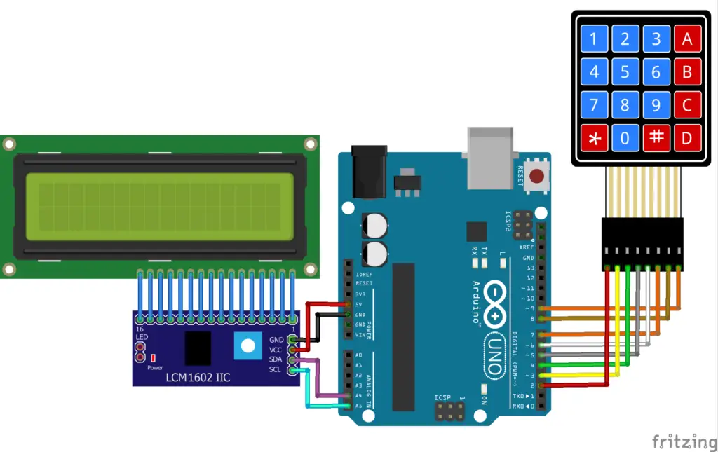
You will adjust the potentiometer until a series of rectangles appear – this will allow you to see your programming results.Īfter you have your first program loaded, and you can see the output on the LCD, you can go back and adjust the contrast control for optimal viewing. This adjustment is made with a small screwdriver. Located on the back of the LCD screen is the I2C interface board, and on the interface is an adjustable potentiometer. You must now adjust that contrast setting. The LCD has an adjustment on it which needs to be approximately set to allow you to see characters on the display. Once you have the four connections to your LCD made, you can power your Arduino, which will provide power to the LCD. The chart below shows the connections needed. The connections include two for power and two for data. How To Connect the I2C LCD to Arduino UNOĬonnecting the Arduino UNO to the I2C interface of the LCD requires only four connections. These pixels can display standard text, numbers, or special characters and can also be programmed to display custom characters easily. The LCD displays each character through a matrix grid of 5×8 pixels. If you happen to have an LCD without an I2C interface incorporated into the design, these can be easily acquired separately. An I2C LCD advantage is that wiring is straightforward, requiring only two data pins to control the LCD.Ī standard LCD requires over ten connections, which can be a problem if your Arduino does not have many GPIO pins available. The module features a controller chip handling I2C communications and an adjustable potentiometer for changing the intensity of the LED backlight. LCDs incorporate a small add-on circuit (backpack) mounted on the back of the LCD module. The character LCD is ideal for displaying text and numbers and special characters. We offer both a 2 x 16 LCD along with the larger 4 x 20 LCD.
#Coding lcd arduino professional
Using an I2C interface, only two connections for an LCD character display are possible with stunning professional results. Adding an external display would typically require several of the limited I/O pins. The ability to interface to external devices readily is very enticing, although the Arduino has a limited number of input/output options. The Arduino family of devices is features rich and offers many capabilities. Dayton Hamvention Previous Years Vendors.

LED Series Dropping Resistor Calculator.

LED Specifications and Application Notes.LED Specifications and Application Notes Expand.LED Spotlight Junior – 18-LED Spotlight Board.NodeMCU IoT Experimenter Prototype Board.


 0 kommentar(er)
